Patchpanels, A/B Switches

IPS-32-front for a/b switches implementation
More Images
  • IPS-32-rear for a/b switches implementation

A/B Switches

The compact IPS 16/32 high bit-rate, high-bandwidth A/B switches are the mainstay of the product family. Latching relays ensure connections are not lost during power failure. Rear-mounting interface modules allow for a wide range of interfaces – eliminating the need for adapters. Perfect for multi-interface environments,  IPS units accommodate fiber, datacom, T1/E1, Analog/VF, balance electrical, coaxial electrical and optical signal types – all in the same 4U (7”H) chassis.

IPS 16/32 Key Features

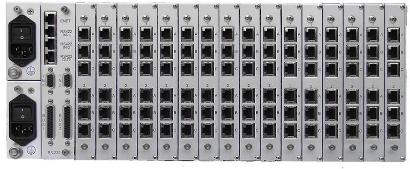
  • Rear mounting of up to 16 interface cards:
  • Signal Types (RS-232/V.24, EIA-530, V.35, RS-449, X.21, DS1/E1/TI PRI or BRI, 10/100BaseT Ethernet, 2/4/6-wire analog
  • Multiple Control Mechanisms (VT-100 terminal, CorScan® control, TCP/IP Ethernet, Telnet, Front panel toggle switch, Contact closure)
  • Switching via magnetic latching relays
  • MTBF greater than 10 million switching actions
  • Dual AC power supply

IPS RC (Redundant Controller)

IPS-RC-FRONT a/b switches

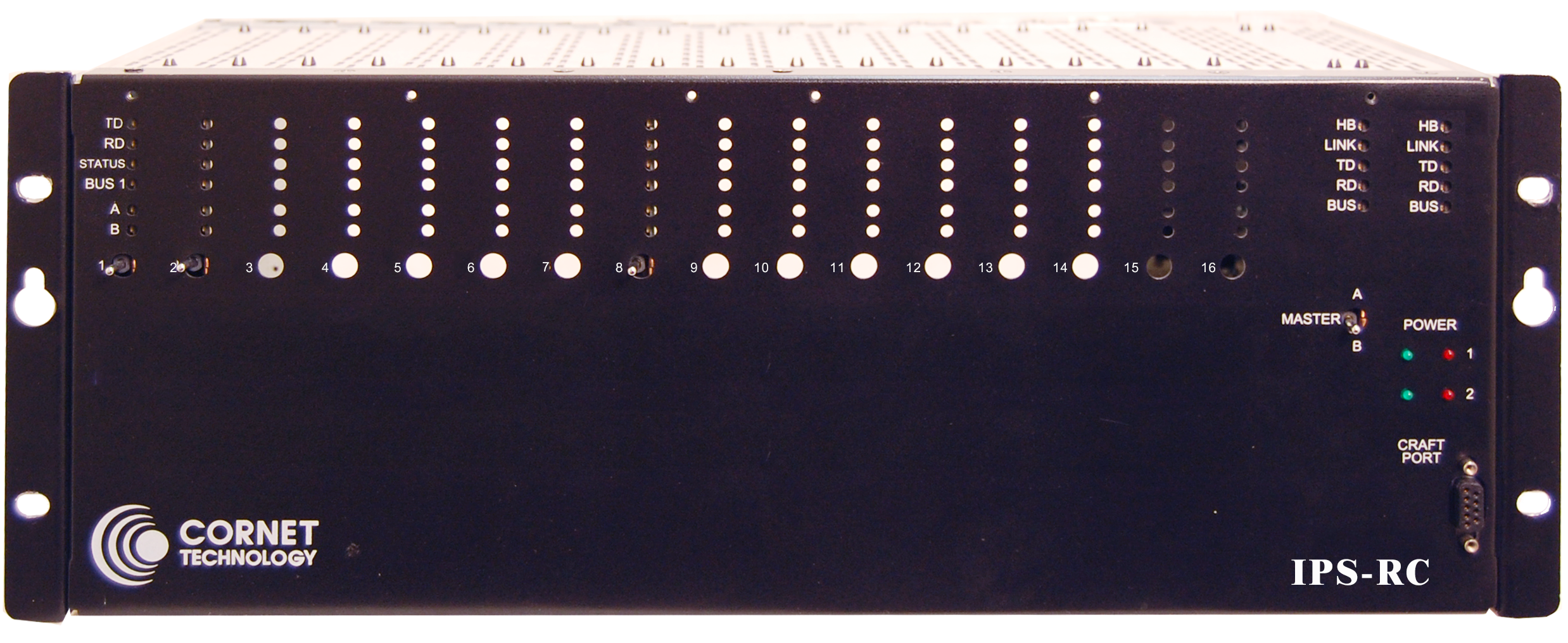
The IPS RC has the same functionality of the IPS 16/32  A/B switch with the addition of dual controller cards. The shared backplane bus connection provides an internal path that ensures each controller has the latest switch status and configuration information. The primary advantage of having dual controllers is that either controller card can assume control. This feature plus the redundant power supplies provide maximum uptime for the system and the shortest repair time possible.

IPS RC Key Feature

  • Dual Controller Cards

Product Specifications

IPS-16/32 and IPS-RC

Chassis:
16 card slots per chassis
Two switches per cards for the IPS-32 and one switch per card for IPS-16
Interfaces/Port:
Quad Card
Copper Path Card
Optical Fiber
Coaxial Electrical
RJ-45
Datacom Interface:
Monitors change of status of RTS, CTS, DSR, CD, and DTR (RS-232, V.25), loss of Rx Data and/or Rx Clock (EIA-530, RS-449), X.21 C&I Lead Status Change, Loss of T, R, and ST
General Switching Methods:
Latching relays
Manual
Software via Cornet Technology's CorScan® control and management system or SNMP

Physical

Dimensions:
4 RU (7” H x 19” W x 8” D)
Weight:
~ 20 lbs.

Power Requirements

Power Supply:
90/230 ± 10% VAC, 47/63Hz
Current:
1 A
Power:
50 VA

Environmental

Operating Temperature:
0°C to +50°C
Non-Operating Temperature:
-20°C to +70°C
Operating Humidity:
98% RH @ +65°C
Non-Operating Humidity:
98% RH @ +65°C (150°F)


Learn About Other Cornet Products and Solutions

Patchpanels, A/B Switches                Patchpanel
C4ISR Solutions                                  Networking                                          Video
Circuit to Packet Solutions                  Radio Crossbanding                             Tactical Switches
Tactical Computers                             Tactical Network Nodes                       Tactical Voice Terminals
Vehicle Communication                      Video Encoders/Decoders/Recorders   
                                                            Home